- Learn SOLIDWORKS 2020
- Tayseer Almattar
- 222字
- 2021-06-24 12:16:41
Sketch planes for features
By default, SOLIDWORKS provides three default planes: the front plane, the top plane, and the right plane. We will use one of these planes to create our first sketch and feature. As we start applying features, these three basic planes may not fulfill our needs for further sketches and features.
Thus, by creating more features, the resulting straight surfaces can also be used by sketching planes. We can use these to create even more sketches and features.
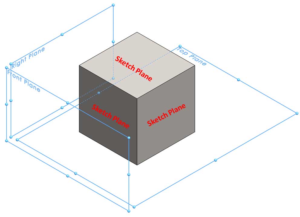
For example, for a new file, we will only have three sketch planes: the default base ones. If we create a cube, each face of the cube will also be a possible sketch plane. Thus, after creating the cube, we will be adding five potential sketch planes for the five new faces of the cube. The following image shows the three base planes, as well as some of the new planes that were created with the new cube. Note that some of the sketch planes may coincide with each other:
We have just learned what features are, which features are used in complex and simple models, and how sketch planes relate to features. Now, let's explore our first set of features, that is, extruded boss and cut.
- Ansible Configuration Management
- Learning Microsoft Azure Storage
- Dreamweaver CS3網頁制作融會貫通
- Mastering Elastic Stack
- RPA(機器人流程自動化)快速入門:基于Blue Prism
- 基于ARM 32位高速嵌入式微控制器
- Hybrid Cloud for Architects
- Lightning Fast Animation in Element 3D
- Blender 3D Printing by Example
- 單片機原理實用教程
- 機器人剛柔耦合動力學
- 網頁設計與制作
- JSP網絡開發入門與實踐
- Arduino創意機器人入門:基于ArduBlock(第2版)
- 探索中國物聯網之路