- Learn SOLIDWORKS 2020
- Tayseer Almattar
- 592字
- 2021-06-24 12:16:35
Fillets and chamfers
In this section, we will discuss making fillet and chamfers for our sketches. Fillets and chamfers can be applied between two sketch entities, usually between two lines. They are defined as follows:
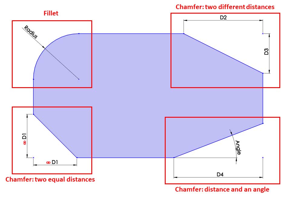
- Fillets: Fillets can be viewed as a type of arc. Thus, they are defined in the same way, that is, with a center and a radius.
- Chamfers: Chamfers can be defined in different ways. These include two equal distances, two different distances, or a distance and an angle.
The following image illustrates the shapes of fillets and chamfers, as well as how they are defined:
To illustrate how to create fillets and chamfers, we will sketch what's shown in the following image:
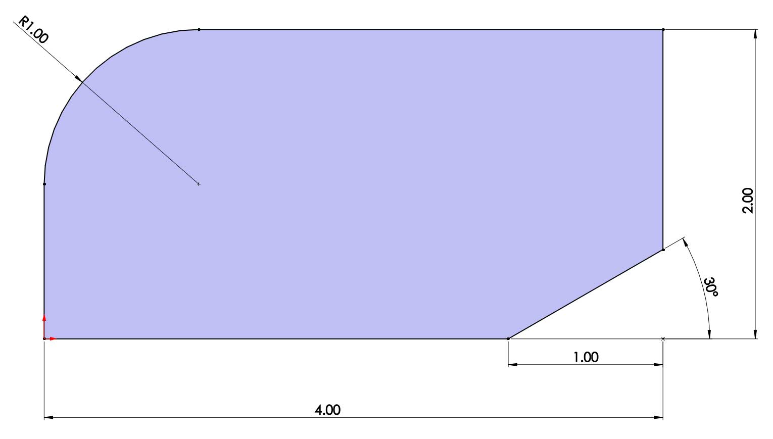
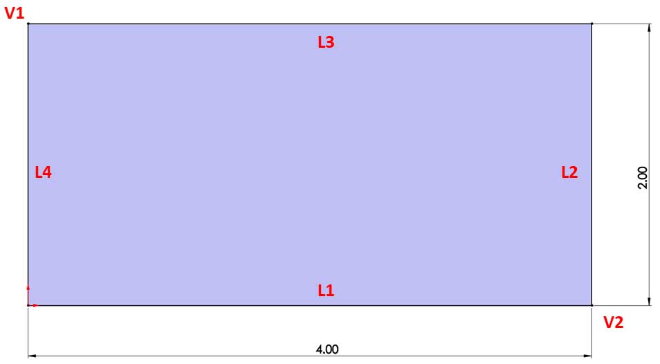
Fillets and chamfers are different than other sketching commands in that we will apply and define them at the same time. Thus, they won't follow our typical procedure of outlining and then defining. To create the sketch, we will use the IPS measurement system. To achieve the preceding sketch, we will need to sketch a 4 x 2-inch rectangle, which will be our starting point. Note that we marked the different lines with the letter L and marked the different vertices with the letter V for ease of reference:
Now, we can start creating the fillet, as follows:
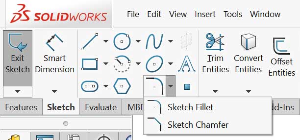
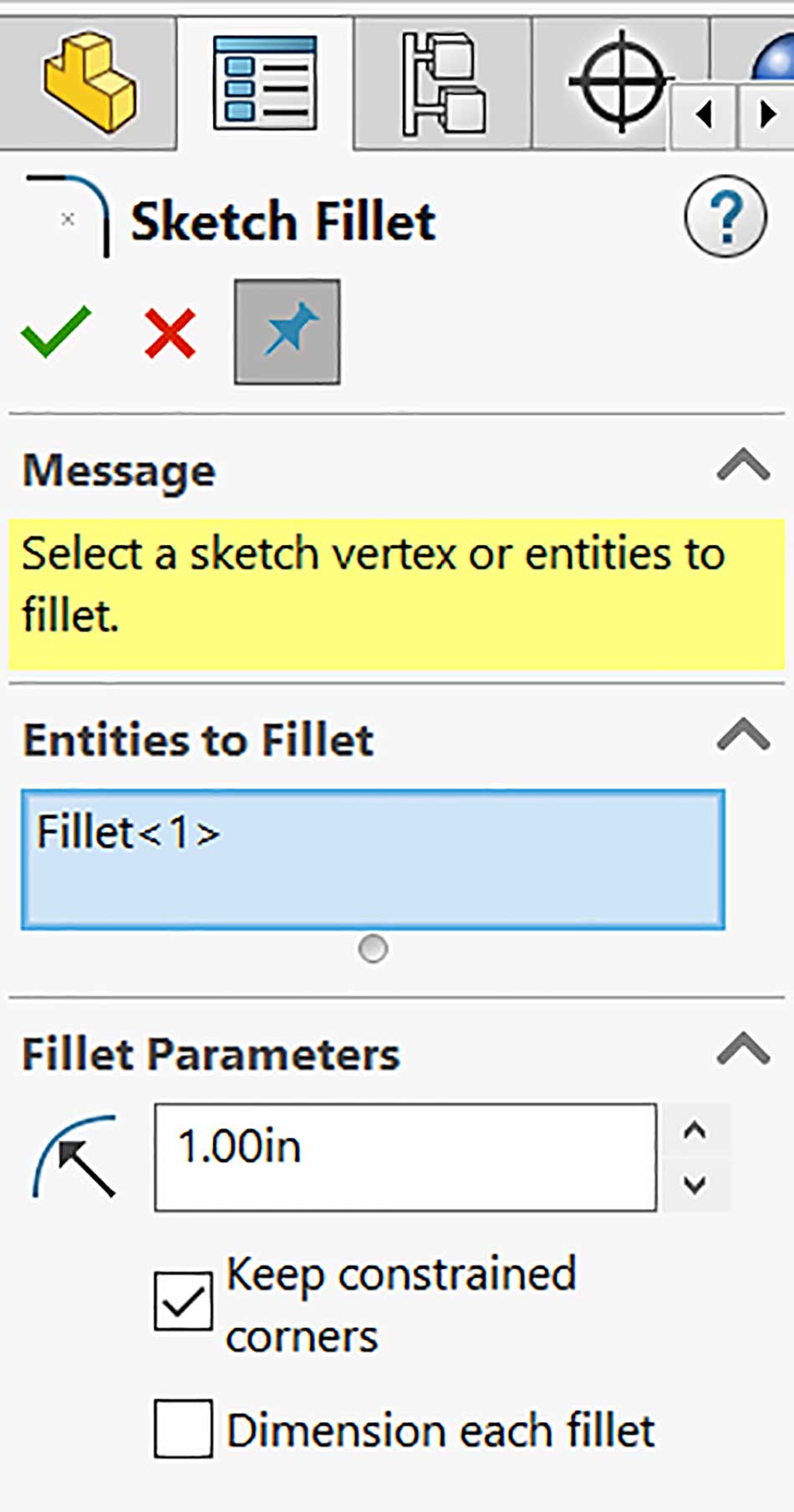
- A sketch is positioned based on a vertex or the two lines around a vertex. Select lines 3 and 4 (L3 and L4) and then select the Sketch Fillet command from the command bar, as follows. Alternatively, we can select vertex 1 (V1) and then select the Sketch Fillet command:
- This will bring up a preview of the fillet on the canvas. You can find more options on the left-hand side, in place of the design tree, as shown in the following screenshot. Under Fillet Parameters, fill in the radius of the fillet as 1 inch. Then, click on the green checkmark. This concludes making the fillet. Now that we've made the fillet, we can press Esc on the keyboard to exit the fillet sketching mode:
Now that we've sketched the fillet, we will move on to sketching the chamfer:
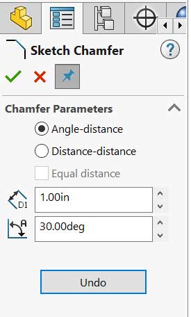
- The chamfer that we had in our final sketch is defined by an angle and a distance. Note that the angle displayed indicates the angle measurement between L2 and the chamfer itself. Thus, hold down Ctrl, select L1, and then select L2. After that, select the Sketch Chamfer command. Similar to the Fillet command, we will get a preview of the chamfer. Also, on the left-hand side, we will find more options that we can use to define our chamfer.
- Select Angle-distance. Then, set the angle to 30 degrees and the distance to 1 inch. Click on the green checkmark afterward:
This concludes how to create fillets and chamfers. In this exercise, we learned what fillets and chamfers are and what defines them, and how to create fillets and chamfers in SOLIDWORKS sketching mode.
Now, we know how to use all the major basic sketching commands. You will use these commands over and over again when working with the software. Now, we will dig deeper into what the different types of definition statuses mean, that is, under defined, fully defined, and over defined.
- 構(gòu)建高質(zhì)量的C#代碼
- Deep Learning Quick Reference
- 蕩胸生層云:C語言開發(fā)修行實錄
- Windows 8應(yīng)用開發(fā)實戰(zhàn)
- 嵌入式Linux上的C語言編程實踐
- 西門子變頻器技術(shù)入門及實踐
- 網(wǎng)絡(luò)安全管理實踐
- 面向?qū)ο蟪绦蛟O(shè)計綜合實踐
- Statistics for Data Science
- 嵌入式操作系統(tǒng)原理及應(yīng)用
- Windows安全指南
- 智慧未來
- FreeCAD [How-to]
- 大話數(shù)據(jù)科學(xué):大數(shù)據(jù)與機(jī)器學(xué)習(xí)實戰(zhàn)(基于R語言)
- 微控制器的選擇與應(yīng)用