- Learn SOLIDWORKS 2020
- Tayseer Almattar
- 573字
- 2021-06-24 12:16:35
Sketching circles and arcs
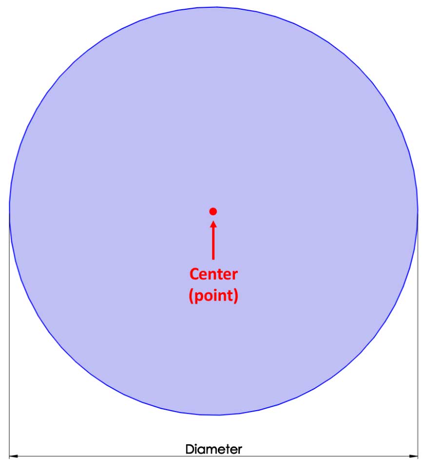
In this section, we will sketch circles and arcs. First, let's break down what defines a circle and an arc. The following image is of a circle. Note that a circle is defined by its Center (a point) and its Diameter:
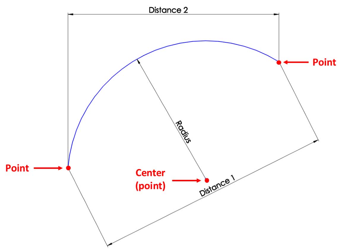
The following image shows an arc, as well as the elements that define it. An arc can be defined by its Center (a point), as well as other points, which indicate the endpoints of the arc. This is in addition to its Radius and various distances:
Each of these elements can be controlled with dimensions or relations. Each point can be understood as a standalone entity that we can use for relations or dimensions.
To illustrate these two commands, we will sketch the following shape:
Similar to what we did previously, we will do outlining and then defining. We will start with the outlining stage, as follows:
- Open a new part file and make sure that the measurement system is set to MMGS (millimeter, gram, second). Note that we have selected MMGS for practice purposes only.
- Navigate to the Sketch mode using any of the default planes (for example, Top Plane).
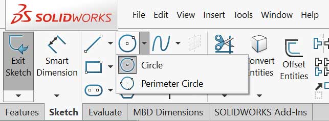
- On the command bar, select the Circle command. Click on the origin, and then move the mouse further to form a circle. Click again to finish drawing the circle:
- Click on the Centerpoint Arc command and follow the instructions shown in the small command image:
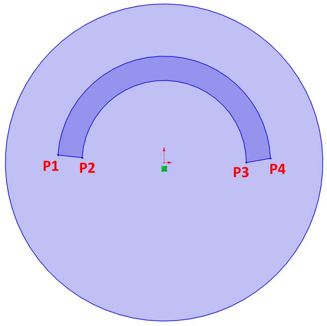
- Connect the endpoints of the arcs using the Line sketch command. The result will be similar to the following image. Note that we indicated the different points of the sketch using the letters P1-P4, which stand for point 1, point 2, and so on:
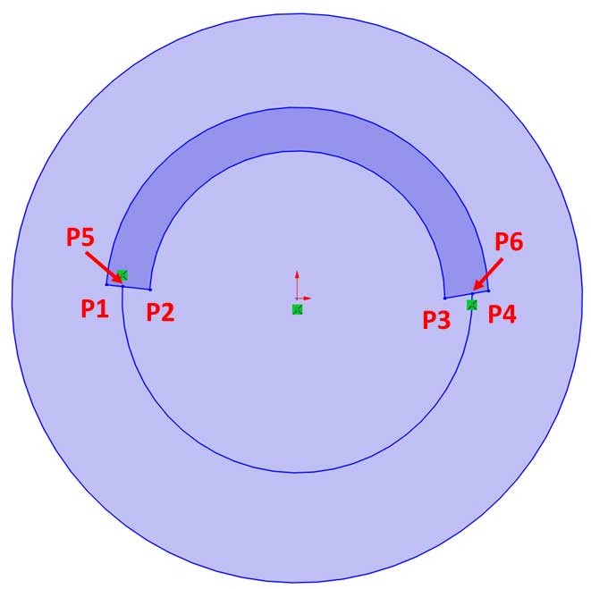
- Use the Centerpoint Arc to create the last lower arc, which links the two lines we created in Step 5, to create the following image:
Now that we've finished outlining, we can start defining the sketch elements in the defining stage. Let's get started:
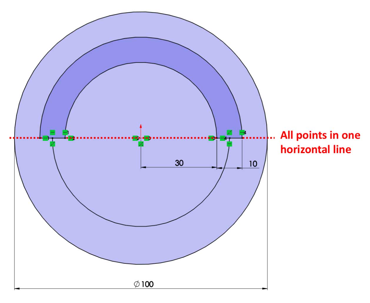
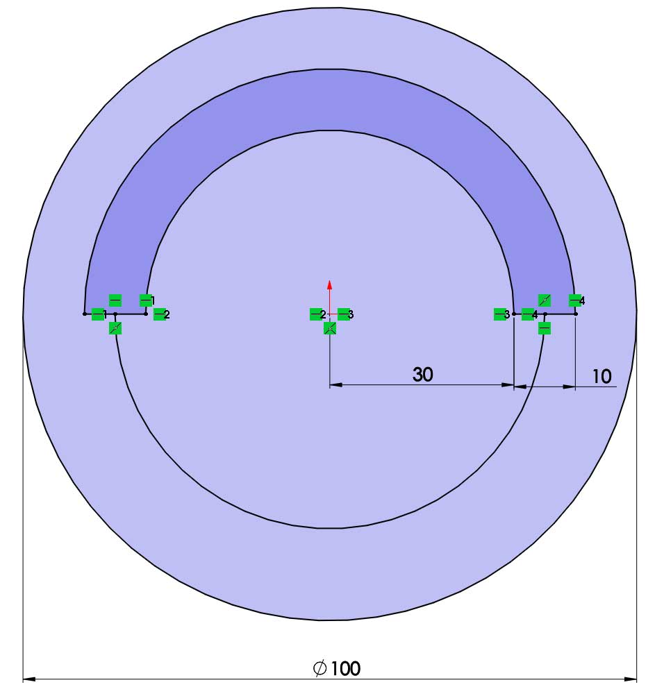
- Note that P1, P2, P3, P4, and the origin are all in a horizontal line in the initial image for this exercise. To do this, select all the points and the origin and select the Horizontal relation. Alternatively, we can do the same in more steps by selecting P1 and the origin and setting the relation to Horizontal. We can then do the same with P2 and the origin, P3 and the origin, and P4 and the origin.
- Set a Midpoint relation between P5 and lines P1 and P2. Do this by selecting the point, P5, and the line around it, and then select the Midpoint relation. Do the same for P6 and lines P3 and P4.
- Set the dimensions shown in the following image using the Smart Dimension function:
This concludes this exercise of using circles and arcs. At this point, our sketch is fully defined. Before moving on, take some time to individually experiment with creating a Perimeter Circle, a Tangent Arc, and a 3 Point Arc. These are some other ways we can create circles and arcs that we did not explore in this exercise. However, all these commands follow the same principles when it comes to making circles and arcs. Now that we've mastered how to create circles and arcs, we will address ellipses and construction lines.